Configuring the EAPs Separately via Omada Controller
CHAPTERS
1. View the Information of the EAP
2. View Clients Connecting to the EAP
|
|
This guide applies to: Omada Controller 2.6.0. |

In addition to global configuration, you can configure the EAPs separately and the configuration results will be applied to a specified EAP device.
To configure a specified EAP, please click the EAP’s name on the Access Points tab or click  of connected EAP on the map. Then you can view the EAP’s detailed information and configure the EAP on the pop-up window.
This guide includes the following contents:
View the Information of the EAP
View the Clients Connecting to the EAP
Configure the EAP
1View the Information of the EAP
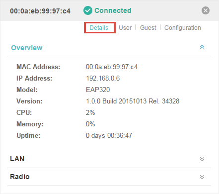
1.1Overview
Click Overview to view the basic information including EAP’s MAC address (or name you set), IP address, model, firmware version, the usage rate of CPU and Memory and uptime (indicates how long the EAP has been running without interruption).
Figure 1-1 Basic Information of the EAP
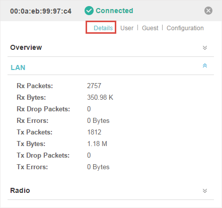
1.2LAN
Click LAN to view the traffic information of the LAN port, including the total number of packets, the total size of data, the total number of packets loss, and the total size of error data in the process of receiving and transmitting data.
Figure 1-2 The Traffic Information of the LAN Port
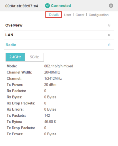
1.3Radio
Click Radio to view the radio information including the frequency band, the wireless mode, the channel width, the channel, and the transmitting power. At 2.4GHz, you can also view parameters of receiving/transmitting data.
Figure 1-3 The Radio Information
2View Clients Connecting to the EAP
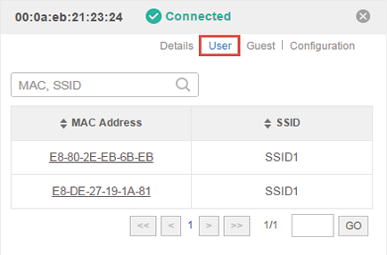
2.1User
The User page displays the information of clients connecting to the SSID with Portal disabled, including their MAC addresses and connected SSIDs. You can click the client’s MAC address to get its connection history.
Figure 2-1 The User Page
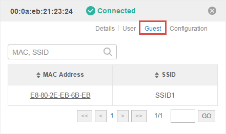
2.2Guest
The Guest page displays the information of clients connecting to the SSID with Portal enabled, including their MAC addresses and connected SSIDs. You can click the client’s MAC address to get its connection history.
Figure 2-2 The Guest Page
The Configuration page allows you to configure the EAP. All the configurations will only take effect on this device.
Figure 3-1 The Configuration Page
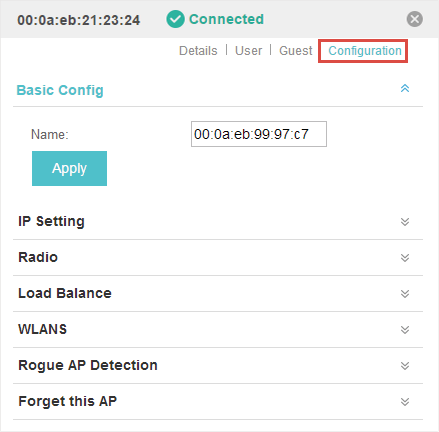
3.1Basic Config
Here you can change the name of the EAP.
Figure 3-2 Basic Config

3.2IP Setting
You can configure an IP address for this EAP. Two options are provided: DHCP and Static.
Figure 3-3 IP Setting
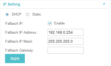
Get a Dynamic IP Address From the DHCP Server
1)Configure your DHCP server.
2)Select DHCP on the page above.
3)Enable the Fallback IP feature. When the device cannot get a dynamic IP address, the fallback IP address will be used.
4)Set IP address, IP mask and gateway for the fallback address and click Apply.
Manually Set a Static IP Address for the EAP
1)Select Static.
2)Set the IP address, IP mask and gateway for the static address and click Apply.
3.3Radio
Radio settings directly control the behavior of the radio in the EAP device and its interaction with the physical medium; that is, how and what type of signal the EAP device emits.
Figure 3-4 Radio Setting
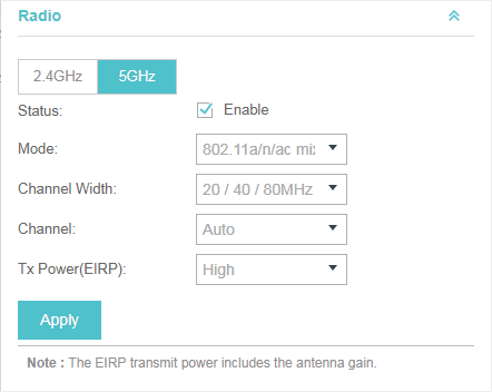
Select the frequency band (2.4GHz/5GHz) and configure the following parameters.
|
Status |
Enabled by default. If you disable the option, the radio on the frequency band will turn off. |
|
Mode |
Select the IEEE 802.11 mode the radio uses. When the frequency of 2.4GHz is selected, 802.11b/g/n mixed, 802.11b/g mixed, and 802.11n only modes are available: 802.11b/g/n mixed: All of 802.11b, 802.11g, and 802.11n clients operating in the 2.4GHz frequency can connect to the EAP device. We recommend you select the 802.11b/g/n mixed mode. 802.11b/g mixed: Both 802.11b and 802.11g clients can connect to the EAP device. 802.11n only: Only 802.11n clients can connect to the EAP device. When the frequency of 5GHz is selected, 802.11 n/ac mixed, 802.11a/n mixed, 802.11 ac onl7, 802.11a only, and 802.11n only modes are available: 802.11n/ac mixed: Both 802.11n clients and 802.11ac clients operating in the 5GHz frequency can connect to the EAP device. 802.11a/n mixed: Both 802.11a clients and 802.11n clients operating in the 5GHz frequency can connect to the EAP device. 802.11ac only: Only 802.11ac clients can connect to the EAP device. 802.11a only: Only 802.11a clients can connect to the EAP device. 802.11n only: Only 802.11n clients can connect to the EAP device. |
|
Channel Width |
Select the channel width of the EAP device. The available options differ among different EAPs. For some EAPs, available options include 20MHz, 40MHz and 20/40MHz. For other EAPs, available options include 20MHz, 40MHz, 80MHz and 20/40/80MHz. The 20/40 MHz and 20/40/80MHz channels enable higher data rates but leave fewer channels available for use by other 2.4GHz and 5GHz devices. When the radio mode includes 802.11n, we recommend you set the channel bandwidth to 20/40 MHz or 20/40/80MHz to improve the transmission speed. |
|
Channel |
Select the channel used by the EAP device to improve wireless performance. The range of available channels is determined by the radio mode and the country setting. If you select Auto for the channel setting, the EAP device scans available channels and selects a channel where the least amount of traffic is detected. |
|
Channel Limit |
For the EAPs that support DFS in EU version, there is a Channel Limit option. If you want to use your EAP outdoors, enable this option to comply with the laws in your country. |
|
Tx Power (EIRP) |
Select the Tx Power (Transmit Power) in the 4 options: Low, Medium, High and Custom. Low, Medium and High are based on the Max TxPower (maximum transmit power. It may vary among different countries and regions). Low: Max TxPower * 20% (round off the value) Medium: Max TxPower * 60% (round off the value) High: Max TxPower Custom: Enter a value manually. |
3.4Load Balance
By setting the maximum number of clients accessing the EAPs, Load Balance helps to achieve rational use of network resources.
Figure 3-5 Load Balance
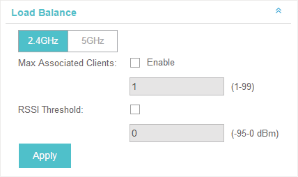
Select the frequency band (2.4GHz/5GHz) and configure the parameters.
|
Max Associated Clients |
Enable this function and specify the maximum number of connected clients. While more clients requesting to connect, the EAP will disconnect those with weaker signals. |
|
RSSI Threshold |
Enable this function and enter the threshold of RSSI (Received Signal Strength Indication). When the clients' signal is weaker than the RSSI Threshold you've set, the clients will be disconnected from the EAP. |
3.5WLANs
You can specify a different SSID name and password to override the previous SSID. After that, clients can only see the new SSID and use the new password to access the network. Follow the steps below to override the SSID.
Figure 3-6 WLANS
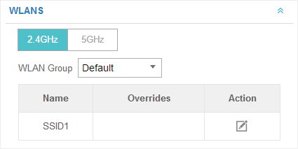
1)Select the frequency band and WLAN group.
2)Click and the following window will pop up.
Figure 3-7 SSID Override
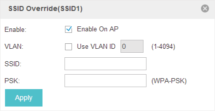
1)Check the box to enable the feature.
2)You can join the overridden SSID in to a VLAN. Check the Use VLAN ID box and specify a VLAN ID.
3)Specify a new name and password for the SSID.
4)Click Apply to save the configuration.
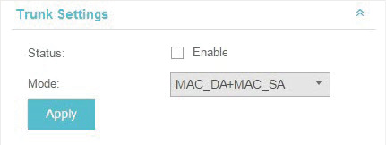
3.6Trunk Settings
Only EAP330 supports this function.
The trunk function can bundles multiple Ethernet links into a logical link to increase bandwidth and improve network reliability.
Figure 3-8 Trunk Setting
|
Status |
Enable this function. The EAP330 has two 1000Mbps Ethernet ports. If the Trunk function is enabled and the ports are in the speed of 1000Mbps Full Duplex, the whole bandwidth of the trunk link is up to 4Gbps (2000Mbps * 2). |
|
Mode |
Select the applied mode of Trunk Arithmetic. • SRC MAC + DST MAC: When this option is selected, the arithmetic will be based on the source and destination MAC addresses of the packets. • DST MAC: When this option is selected, the arithmetic will be based on the destination MAC addresses of the packets. • SRC MAC: When this option is selected, the arithmetic will be based on the source MAC addresses of the packets. |
With this option enabled, the EAP device will detect rogue APs in all channels.
Figure 3-9 Rogue AP Detection

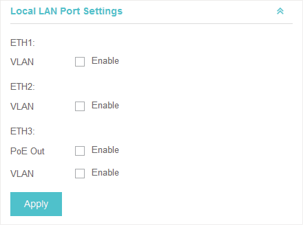
You can configure the LAN port of the EAP.
Figure 3-10 Local LAN Port Settings
|
VLAN |
Enable this feature and specify the VLAN that the EAP is added to, and then the hosts connected to this EAP can only communicate with the devices in this VLAN. The valid values are from 1 to 4094, and the default is 1. |
|
PoE Out |
If your EAP has PoE OUT port, you can enable this option to supply power to the connected device on this port. The EAP that has no PoE OUT port does not support this feature. |
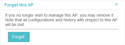
3.9Forget this AP
If you no longer want to manage this EAP, you may remove it. All the configurations and history about this EAP will be deleted. It is recommended to back up the configurations of this EAP before you forget it.
Figure 3-11 Forget This AP