Configuring OAM
CHAPTERS
2. Ethernet OAM Configurations
5. Appendix: Default Parameters
|
|
This guide applies to: T2600G-18TS v2 or above, T2600G-28TS v3 or above, T2600G-28MPS v3 or above, T2600G-28SQ v1 or above, T2600G-52TS v3 or above. |

1.1Overview
Ethernet OAM (Operation, Administration, and Maintenance) is a Layer 2 protocol for monitoring and troubleshooting Ethernet networks. It can monitor link performance, monitor faults and generate alarms so that a network administrator can manage the network effectively. TP-Link switches support EFM OAM which is defined in IEEE 802.3ah.
The following basic concepts of OAM will be introduced: OAM entity, OAMPDUs (OAM Protocol Data Units), and OAM connection.
OAM Entity
A port that is enabled with OAM on the switch is called an OAM entity.
OAMPDUs
Through OAMPDUs exchanged between OAM entities, failure conditions on the network are reported to network administrators. The OAMPDUs are defined as follows:
Information OAMPDU: The Information OAMPDU is used to send state information, such as local information, remote information, and user-defined information, to the remote OAM entity for maintaining OAM connection.
Event Notification OAMPDU: The Event Notification OAMPDU is used for the Link Monitoring feature. The local OAM entity can use the Event Notification OAMPDU to notify the remote OAM entity that a fault has occurred to the link.
Loopback Control OAMPDU: Loopback Control OAMPDU is used for the Remote Loopback feature. The local OAM entity can control OAM remote loopback state of the remote OAM entity through the Loopback Control OAMPDU.
OAM Connection
OAM connection is established between OAM entities before OAM works. An OAM entity can operate in two modes: active and passive. Only the active OAM entity can initiate an OAM connection; the passive OAM entity waits and responds to OAM connection establishment requests. So at least one of the two entities should be in active mode.
Figure 1-1 OAM Connection Establishment
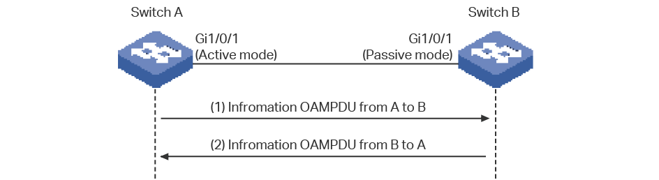
As the above figure shows, the OAM entity on Switch A is in active mode, and that on Switch B is in passive mode. Switch A initiates an OAM connection by sending an Information OAMPDU. Switch B compares the OAM information in the received OAMPDU with its own and sends back an Information OAMPDU to Switch A. If the OAM information of the two entities matches, an OAM connection will be established. After that, the two OAM entities will exchange Information OAMPDUs periodically to keep the OAM connection valid.
1.2Supported Features
The switch supports the following OAM features: Link Monitoring, Remote Failure Indication (RFI), and Remote Loopback.
Link Monitoring is for monitoring link performance under various circumstances. When problems are detected on the link, the OAM entity will send its remote peer the Event Notification OAMPDUs to report link events.
The link events are described as follows:
Table 1-1OAM Link Events
|
OAM Link Events |
Definition |
|
Error Symbol Period |
An Error Symbol Period event occurs if the number of error symbols exceeds the defined threshold within a specific period of time. |
|
Error Frame |
An Error Frame event occurs if the number of error frames exceeds the defined threshold within a specific period of time. |
|
Error Frame Period |
An Error Frame Period event occurs if the number of error frames in a specific number of received frames exceeds the defined threshold. |
|
Error Frame Seconds |
An Error Frame Seconds event occurs if the number of error frame seconds exceeds the threshold within a specific period of time. A second is defined as an error frame second if error frames occur within that second. |
Remote Failure Indication (RFI)
With Remote Failure Indication, an OAM entity can send the failure conditions of the link, such as disruption in traffic because of the device failure, to its peer through Information OAMPDUs. This allows the network administrator to stay informed of the link faults and take action quickly. The switch supports two kinds of failure conditions:
Dying Gasp: An unrecoverable fault, such as power failure, occurs.
Critical Event: Unspecified critical event occurs.
With Remote Loopback, administrators can test link performance including the delay, jitter, and frame loss rate during installation or troubleshooting.
Figure 1-2 Remote Loopback
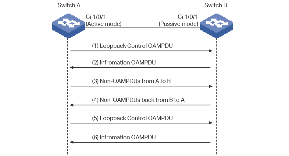
As the above figure shows, the OAM connection has been established between the two entities. The OAM entity on Switch A is in active mode, and that on Switch B is in passive mode.
The working mechanism of Remote Loopback is as follows:
1)Switch A sends a Loopback Control OAMPDU to put the peer into remote loopback mode. Note that at least one of the two entities should be configured in active mode because only the entity in active mode can generate Loopback Control OAMPDU.
2)After receiving the Loopback Control OAMPDU, Switch B turns into remote loopback mode and sends an Information OAMPDU to inform its state updating.
3)Switch A sends Non-OAMPDU packets to Switch B for link testing.
4)Switch B receives the testing packets and sends back these packets along the original path. Through these returned packets, administrators can test the link performance.
5)When Remote Loopback is finished, Switch A sends a Loopback Control OAMPDU to disable the remote loopback mode on Switch B.
6)Switch B receives the Loopback Control OAMPDU and exits remote loopback mode. Besides, Switch B sends an Information OAMPDU to inform its state updating.
TP-Link switches can act as Switch A and initiate Remote Loopback request.
To complete OAM configurations, follow these steps:
1)Enable OAM and configure OAM mode on the port.
2)Configure the following OAM features according to your needs:
Link Monitoring
Remote Failure Indication (RFI)
Remote Loopback
3)View the OAM status on the port.
2.1Using the GUI
2.1.1Enabling OAM and Configuring OAM Mode
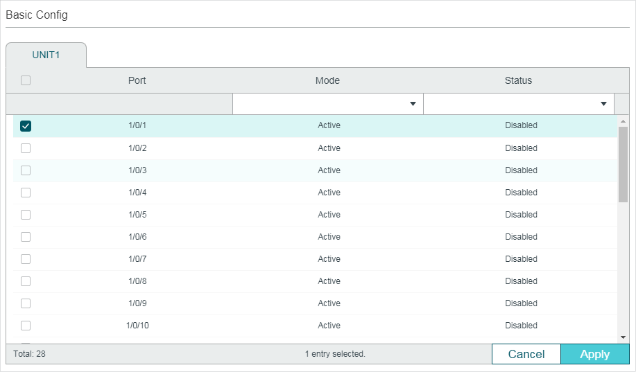
Choose the menu MAINTENANCE > Ethernet OAM > Basic Config > Basic Config to load the following page.
Figure 2-1 Basic Configuration
Follow these steps to complete the basic OAM configuration:
1)Select one or more ports, configure the OAM mode and enable OAM.
|
Mode |
Select OAM mode for the port. Active: The port in this mode can initiate OAM connection. It is the default setting. Passive: The port in this mode cannot initiate OAM connection or send loopback control OAMPDUs. Note: OAM connection cannot be established between two ports in passive mode. Make sure that at least one side is in active mode. |
|
Status |
Enable or disable OAM on the port. By default, it is disabled. |
2)Click Apply.
2.1.2Configuring Link Monitoring
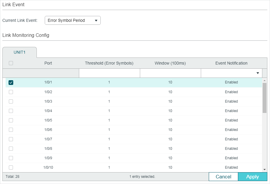
Choose the menu MAINTENANCE > Ethernet OAM > Link Monitoring > Link Monitoring to load the following page.
Figure 2-2 Configure Link Monitoring
Follow these steps to configure Link Monitoring:
1)In the Link Event section, select a Link Event type to configure.
|
Current Link Event |
Select Link Event type. The following options are provided: Error Symbol Period: An Error Symbol Period event occurs if the number of error symbols exceeds the defined threshold within a specific period of time. Error Frame: An Error Frame event occurs if the number of error frames exceeds the defined threshold within a specific period of time. Error Frame Period: An Error Frame Period event occurs if the number of error frames in a specific number of received frames exceeds the defined threshold. Error Frame Seconds: An Error Frame Seconds event occurs if the number of error frame seconds exceeds the threshold within a specific period of time. A second is defined as an error frame second if error frames occur within that second. |
2)In the Link Monitoring Config section, select one or more ports, and configure the threshold and period for the selected link event.
|
Threshold |
Specify the threshold for the selected link event. Threshold (Error Symbols): If you select Error Symbol Period as the link event type, specify the threshold of received error symbols within a specific period of time. Valid error frame values are from 1 to 4294967295, and the default value is 1. Threshold (Error Frames): If you select Error Frame or Error Frame Period as the link event type, specify the threshold of error frames within a specific period of time or in specific number of received frames. Valid error frame values are from 1 to 4294967295, and the default value is 1. Threshold (Error Seconds): If you select Error Frame Seconds as the link event type, specify the threshold of error frame seconds. Valid values are from 1 to 900, and the default value is 1. |
|
Window |
Specify the period for the selected link event. Window (100ms): If you select Error Symbol Period, Error Frame or Error Frame Seconds as the link event type, specify the time period in units of 100ms (for example, 2 refers to 200ms), in which if the received errors exceed the threshold, a link event will be generated. For Error Symbol Period and Error Frame, valid values are from 10*100 to 600*100 ms. For Error Frame Seconds, valid values are from 100*100 to 9000*100 ms. Window (Frames): If you select Error Frame Period as the link event type, specify the number of frames, in which if the frame errors exceed the threshold, a link event will be generated. Valid values are from 148810 to 89286000 frames, and the default value is 1488100 frames. |
|
Event Notification |
Enable or disable notifications to report the link event. By default, all types of link event can be reported. |
3)Click Apply.
2.1.3Configuring RFI
Choose the menu MAINTENANCE > Ethernet OAM > Remote Failure Indication to load the following page.
Figure 2-3 Configure RFI
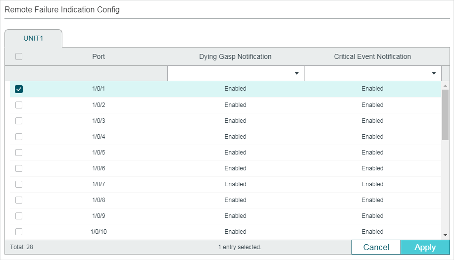
Follow these steps to configure Remote Failure Indication:
1)Select one or more ports and configure the Dying Gasp Notification and Critical Event Notification features.
|
Dying Gasp Notification |
With Dying Gasp Notification enabled, if the switch detects an unrecoverable fault on the network, it will report this condition locally and send Information OAMPDU to notify the peer. |
|
Critical Event Notification |
With Critical Event Notification enabled, if the switch detects an unspecified critical event occurs, it will report this condition locally and send Information OAMPDU to notify the peer. |
2)Click Apply.
2.1.4Configuring Remote Loopback
Choose the menu MAINTENANCE > Ethernet OAM > Remote Loopbak to load the following page.
Figure 2-4 Configure Remote Loopback
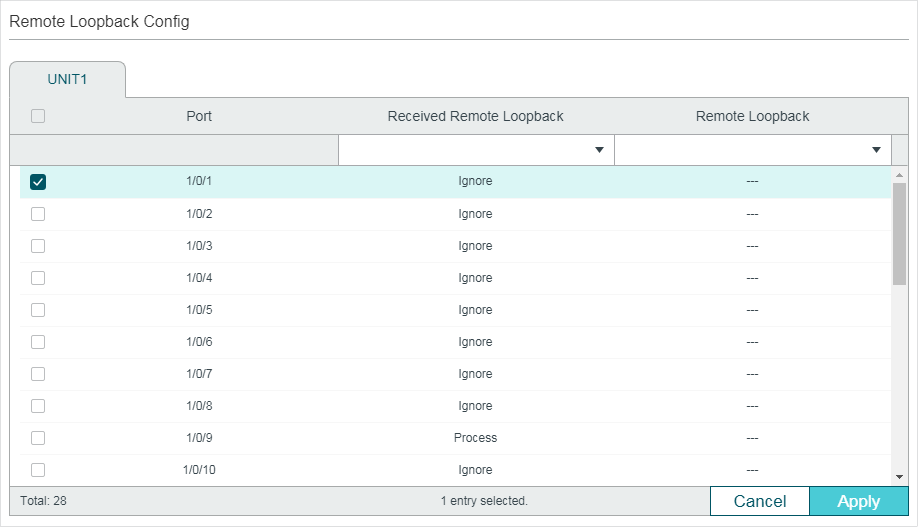
Follow these steps to configure Remote Loopback:
1)Select one or more ports and configure the relevant options.
|
Received Remote Loopback |
Choose to ignore or to process the received remote loopback requests. |
|
Remote Loopback |
Start or stop the remote loopback process. The port to be configured should be in active mode and has established OAM connection with the peer. Start: Request the remote peer to start the OAM remote loopback mode. Stop: Request the remote peer to stop the OAM remote loopback mode. |
2)Click Apply.
2.1.5Viewing OAM Status
Choose the menu MAINTENANCE > Ethernet OAM > Basic Config > Discovery Info to load the following page.
Figure 2-5 View OAM Status
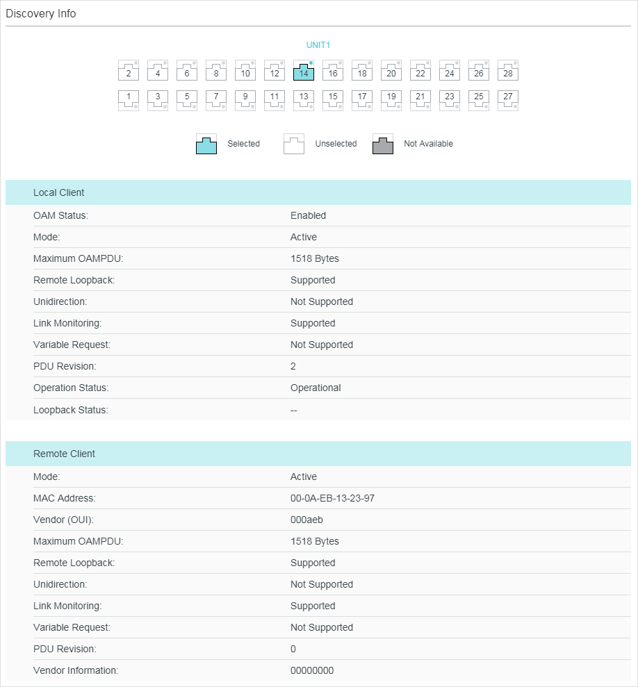
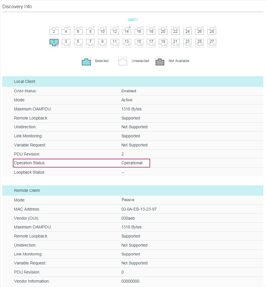
Select a port to view whether the OAM connection is established with the peer. Additionally, you can view the OAM information of the local and the remote entities.
The OAM information of the local entity is as follows:
|
OAM Status |
Displays whether OAM is enabled. |
|
Mode |
Displays the OAM mode of the local entity. |
|
Maximum OAMPDU |
Displays the maximum size of OAMPDU. |
|
Remote Loopback |
Displays whether the local entity supports Remote Loopback. |
|
Unidirection |
Displays whether the local entity supports Unidirection. |
|
Link Monitoring |
Displays whether the local entity supports Link Monitoring. |
|
Variable Request |
Displays whether the local entity supports Variable Request. |
|
PDU Revision |
Displays the PDU Revision of the local entity. |
|
Operation Status |
Displays the status of OAM connection: Disable: OAM is disabled on the port. LinkFault: The link between the local entity and the remote entity is down. PassiveWait: The port is in passive mode and is waiting to see if the peer device is OAM capable. ActiveSendLocal: The port is in active mode and is sending local information. SendLocalAndRemote: The local port has discovered the peer but has not yet accepted or rejected the configuration of the peer. SendLocalAndRemoteOK: The local device agrees the OAM peer entity. PeeringLocallyRejected: The local OAM entity rejects the remote peer OAM entity. PeeringRemotelyRejected: The remote OAM entity rejects the local device. NonOperHalfDuplex: Ethernet OAM is enabled but the port is in half-duplex operation. You should configure the port as a full-duplex port. Operational: OAM connection is established with the peer and OAM works normally. |
|
Loopback Status |
Displays the loopback status. No Loopback: Neither the local entity nor the remote entity is in the loopback mode. Local Loopback: The local entity is in the loopback mode. Remote Loopback: The remote entity is in the loopback mode. |
The OAM information of the remote entity is as follows:
|
Mode |
Displays the OAM mode of the remote entity. |
|
MAC Address |
Displays the MAC address of the remote entity. |
|
Vendor (OUI) |
Displays the Vendor’s OUI of the remote entity. |
|
Maximum OAMPDU |
Displays the maximum size of OAMPDU. |
|
Remote Loopback |
Displays whether the remote entity supports Remote Loopback. |
|
Unidirection |
Displays whether the remote entity supports Unidirection. |
|
Link Monitoring |
Displays whether the remote entity supports Link Monitoring. |
|
Variable Request |
Displays whether the remote entity supports Variable Request. |
|
PDU Revision |
Displays the PDU Revision of the remote entity. |
|
Vendor Information |
Displays the vendor information of the remote entity. |
2.2Using the CLI
2.2.1Enabling OAM and Configuring OAM Mode
Follow these steps to enable OAM and configure OAM mode on the port:
|
Step 1 |
configure Enter global configuration mode. |
|
Step 2 |
interface {fastEthernet port | range fastEthernet port-list | gigabitEthernet port | range gigabitEthernet port-list | ten-gigabitEthernet port | range ten-gigabitEthernet port-list} Enter interface configuration mode. |
|
Step 3 |
ethernet-oam Enable OAM on the port. |
|
Step 4 |
ethernet-oam mode { passive | active } Configure the OAM mode of the port. passive: Specify the OAM mode as passive. The port in this mode cannot initiate OAM connection or send Loopback Control OAMPDU. active: Specify the OAM mode as active. The port in this mode can initiate OAM connection. It is the default setting. Note: OAM connection cannot be established between two ports in passive mode. Make sure that at least one side is in active mode. |
|
Step 5 |
show ethernet-oam configuration [ interface fastEthernet { port | port-list } | interface gigabitEthernet { port | port-list } | ten-gigabitEthernet { port | port-list } ] Verify the OAM configuration. |
|
Step 6 |
end Return to privileged EXEC mode. |
|
Step 7 |
copy running-config startup-config Save the settings in the configuration file. |
The following example shows how to enable OAM and configure the OAM mode as passive on port 1/0/1.
Switch#configure
Switch(config)#interface gigabitEthernet 1/0/1
Switch(config-if)#ethernet-oam
Switch(config-if)#ethernet-oam mode passive
Switch(config-if)#show ethernet-oam configuration interface gigabitEthernet 1/0/1
Gi1/0/1
-----------------------------------------------------------
OAM : Enabled
Mode : Passive
...
Switch(config-if)#end
Switch#copy running-config startup-config
2.2.2Configuring Link Monitoring
With Link Monitoring, the following link events can be reported: Error Symbol Period, Error Frame, Error Frame Period, Error Frame Seconds.
Configuring Error Symbol Period Event
An Error Symbol Period event occurs if the number of symbol errors exceeds the defined threshold within a specific period of time.
Follow these steps to configure the Error Symbol Period event:
|
Step 1 |
configure Enter global configuration mode. |
|
Step 2 |
interface {fastEthernet port | range fastEthernet port-list | gigabitEthernet port | range gigabitEthernet port-list | ten-gigabitEthernet port | range ten-gigabitEthernet port-list} Enter interface configuration mode. |
|
Step 3 |
ethernet-oam link-monitor symbol-period [ threshold threshold ] [ window window ] [notify {disable | enable}] Configure the relevant parameters of Error Symbol Period event. threshold: Specify the threshold of received symbol errors within a specific period of time. Valid values are from 1 to 4294967295, and the default value is 1. window: Specify the time period in units of 100ms (for example, 2 refers to 200ms), in which if the received errors exceed the threshold, a link event will be generated. Valid values are from 10*100 to 600*100 ms, and the default value is 10*100 ms. disable | enable: Enable or disable notifications to report the link event. By default, it is enabled. |
|
Step 4 |
show ethernet-oam configuration [ interface fastEthernet { port | port-list } | interface gigabitEthernet { port | port-list } | interface ten-gigabitEthernet { port | port-list }] Verify the OAM configuration. |
|
Step 5 |
end Return to privileged EXEC mode. |
|
Step 6 |
copy running-config startup-config Save the settings in the configuration file. |
The following example shows how to enable Error Frame event notification and configure the threshold as 1 and the window as 1000 ms (10*100 ms) on port 1/0/1:
Switch#configure
Switch(config)#interface gigabitEthernet 1/0/1
Switch(config-if)#ethernet-oam link-monitor symbol-period threshold 1 window 10 notify enable
Switch(config-if)#show ethernet-oam configuration interface gigabitEthernet 1/0/1
Gi1/0/1
-----------------------------------------------------------
...
Symbol Period Error
Notify State : Enabled
Window : 1000 milliseconds
Threshold : 1 Error Symbol
...
Switch(config-if)#end
Switch#copy running-config startup-config
Configuring Error Frame Event
An Error Frame event occurs if the number of frame errors exceeds the defined threshold within a specific period of time.
Follow these steps to configure the Error Frame event:
|
Step 1 |
configure Enter global configuration mode. |
|
Step 2 |
interface {fastEthernet port | range fastEthernet port-list | gigabitEthernet port | range gigabitEthernet port-list | ten-gigabitEthernet port | range ten-gigabitEthernet port-list} Enter interface configuration mode. |
|
Step 3 |
ethernet-oam link-monitor frame [ threshold threshold ] [ window window ] [ notify {disable | enable}] Configure the relevant parameters of Error Frame event. threshold: Specify the threshold of received frame errors within a specific period of time. Valid values are from 1 to 4294967295, and the default value is 1. window: Specify the time period in units of 100ms (for example, 2 refers to 200ms), in which if the number of received errors exceeds the threshold, a link event will be generated. Valid values are from 10*100 to 600*100 ms, and the default value is 10*100 ms. disable | enable: Enable or disable notifications to report the link event. By default, it is enabled. |
|
Step 4 |
show ethernet-oam configuration [ interface fastEthernet { port | port-list } | interface gigabitEthernet { port | port-list } | ten-gigabitEthernet { port | port-list }] Verify the OAM configuration. |
|
Step 5 |
end Return to privileged EXEC mode. |
|
Step 6 |
copy running-config startup-config Save the settings in the configuration file. |
The following example shows how to enable Error Frame notification and configure the threshold as 1 and the window as 2000 ms (20*100 ms) on port 1/0/1:
Switch#configure
Switch(config)#interface gigabitEthernet 1/0/1
Switch(config-if)#ethernet-oam link-monitor frame threshold 1 window 20 notify enable
Switch(config-if)#show ethernet-oam configuration interface gigabitEthernet 1/0/1
Gi1/0/1
-----------------------------------------------------------
...
Frame Error
Notify State : Enabled
Window : 2000 milliseconds
Threshold : 1 Error Frame
...
Switch(config-if)#end
Switch#copy running-config startup-config
Configuring Error Frame Period Event
An Error Frame Period event occurs if the number of frame errors in specific number of received frames exceeds the defined threshold.
Follow these steps to configure the Error Frame Period event:
|
Step 1 |
configure Enter global configuration mode. |
|
Step 2 |
interface {fastEthernet port | range fastEthernet port-list | gigabitEthernet port | range gigabitEthernet port-list | ten-gigabitEthernet port | range ten-gigabitEthernet port-list} Enter interface configuration mode. |
|
Step 3 |
ethernet-oam link-monitor frame-period [threshold threshold] [window window] [notify {disable | enable}] Configure the relevant parameters of Error Frame Period. threshold: Specify the threshold of received symbol errors in specific number of received frames. Valid values are from 1 to 4294967295, and the default value is 1. window: Specify the number of frames, in which if the frame errors exceed the threshold, a link event will be generated. Valid values are from 148810 to 89286000, and the default value is 1488100. disable | enable: Enable or disable the port to report the failure condition. |
|
Step 4 |
show ethernet-oam configuration [ interface fastEthernet { port | port-list } | interface gigabitEthernet { port | port-list } | ten-gigabitEthernet { port | port-list } ] Verify the OAM configuration. |
|
Step 5 |
end Return to privileged EXEC mode. |
|
Step 6 |
copy running-config startup-config Save the settings in the configuration file. |
The following example shows how to enable Error Frame Period notification and configure the threshold as 1 and the window as 1488100 on port 1/0/1:
Switch#configure
Switch(config)#interface gigabitEthernet 1/0/1
Switch(config-if)#ethernet-oam link-monitor frame-period threshold 1 window 1488100 notify enable
Switch(config-if)#show ethernet-oam configuration interface gigabitEthernet 1/0/1
Gi1/0/1
-----------------------------------------------------------
...
Frame Period Error
Notify State : Enabled
Window : 1488100 Frames
Threshold : 1 Error Frame
...
Switch(config-if)#end
Switch#copy running-config startup-config
Configuring Error Frame Seconds Event
An Error Frame Seconds event occurs if the number of error frame seconds exceeds the threshold within a specific period of time. A second is called an error frame second if error frames occur in the second.
Follow these steps to configure Error Frame Seconds event:
|
Step 1 |
configure Enter global configuration mode. |
|
Step 2 |
interface {fastEthernet port | range fastEthernet port-list | gigabitEthernet port | range gigabitEthernet port-list | ten-gigabitEthernet port | range ten-gigabitEthernet port-list} Enter interface configuration mode. |
|
Step 3 |
ethernet-oam link-monitor frame-seconds [ threshold threshold ] [ window window ] [ notify {disable | enable}] Configure the relevant parameters of Error Frame Period. threshold: Specify the threshold of received error frame seconds within a specific period of time. Valid values are from 1 to 900, and the default value is 1. window: Specify the period time in 100ms, in which if the received errors exceed the threshold, a link event will be generated. Valid values are from 100*100 to 9000*100 ms, and the default value is 600*100 ms. disable | enable : Enable or disable the port to report the failure condition. |
|
Step 4 |
show ethernet-oam configuration [ interface fastEthernet { port | port-list } | interface gigabitEthernet { port | port-list } | ten-gigabitEthernet { port | port-list } ] Verify the OAM configuration. |
|
Step 5 |
end Return to privileged EXEC mode. |
|
Step 6 |
copy running-config startup-config Save the settings in the configuration file. |
The following example shows how to enable Error Frame Seconds notification and configure the threshold as 1 and the window as 80000 ms (800*100 ms)on port 1/0/1:
Switch#configure
Switch(config)#interface gigabitEthernet 1/0/1
Switch(config-if)#ethernet-oam link-monitor frame-seconds threshold 1 window 800 notify enable
Switch(config-if)#show ethernet-oam configuration interface gigabitEthernet 1/0/1
Gi1/0/1
-----------------------------------------------------------
...
Frame Seconds Error
Notify State : Enabled
Window : 80000 milliseconds
Threshold : 1 Error Seconds
...
Switch(config-if)#end
Switch#copy running-config startup-config
2.2.3Configuring Remote Failure Indication
Follow these steps to configure Remote Failure Indication:
|
Step 1 |
configure Enter global configuration mode. |
|
Step 2 |
interface {fastEthernet port | range fastEthernet port-list | gigabitEthernet port | range gigabitEthernet port-list | ten-gigabitEthernet port | range ten-gigabitEthernet port-list} Enter interface configuration mode. |
|
Step 3 |
ethernet-oam remote-failure { dying-gasp | critical-event } notify { disable | enable } Configure the Dying Gasp Notification and Critical Event Notification features on the port. dying-gasp: Enable Dying Gasp Notification, and if the switch detects an unrecoverable fault on the network, such as power failure, occurs, it will send Information OAMPDU to notify the peer. critical-event: Enable Critical Event Notification, and if the switch detects an unspecified critical event occurs, it will send Information OAMPDU to notify the peer. disable | enable: Enable or disable notification to report the link events. |
|
Step 4 |
show ethernet-oam configuration [ interface fastEthernet { port | port-list } | interface gigabitEthernet { port | port-list } | ten-gigabitEthernet { port | port-list }] Verify the OAM configuration. |
|
Step 5 |
end Return to privileged EXEC mode. |
|
Step 6 |
copy running-config startup-config Save the settings in the configuration file. |
The following example shows how to enable Dying Gasp and Critical Event on port 1/0/1:
Switch#configure
Switch(config)#interface gigabitEthernet 1/0/1
Switch(config-if)#ethernet-oam remote-failure dying-gasp notify enable
Switch(config-if)#ethernet-oam remote-failure critical-event notify enable
Switch(config-if)#show ethernet-oam configuration interface gigabitEthernet 1/0/1
Gi1/0/1
-----------------------------------------------------------
...
Dying Gasp : Enabled
Critical Event : Enabled
...
Switch(config-if)#end
Switch#copy running-config startup-config
2.2.4Configuring Remote Loopback
Follow these steps to configure Remote Loopback:
|
Step 1 |
configure Enter global configuration mode. |
|
Step 2 |
interface {fastEthernet port | range fastEthernet port-list | gigabitEthernet port | range gigabitEthernet port-list | ten-gigabitEthernet port | range ten-gigabitEthernet port-list} Enter interface configuration mode. |
|
Step 3 |
ethernet-oam remote-loopback received-remote-loopback { process | ignore } Configure the port to ignore or to process the received remote loopback request. |
|
Step 4 |
ethernet-oam remote-loopback { start | stop } Request the remote peer to start or stop the OAM remote loopback mode. The port to be configured here should be in active mode that has established OAM connection with the peer. |
|
Step 5 |
show ethernet-oam configuration [ interface fastEthernet { port | port-list } | interface gigabitEthernet { port | port-list } | ten-gigabitEthernet { port | port-list }] Verify the OAM configuration. |
|
Step 6 |
end Return to privileged EXEC mode. |
|
Step 7 |
copy running-config startup-config Save the settings in the configuration file. |
The following example shows how to start the OAM remote loopback mode of the peer on port 1/0/1:
Switch#configure
Switch(config)#interface gigabitEthernet 1/0/1
Switch(config-if)# ethernet-oam remote-loopback start
2.2.5Verifying OAM Connection
On privileged EXEC mode or any other configuration mode, you can use the following command to view whether the OAM connection is established with the peer. Additionally, you can view the OAM information of the local entity and the remote entity.
|
show ethernet-oam status [ interface fastEthernet { port | port-list } | interface gigabitEthernet { port | port-list } | ten-gigabitEthernet { port | port-list }] View the OAM status and the relevant information of the specified port, including the local entity and the remote entity. The displayed OAM information of the local entity is as follows: OAM: Displays whether OAM is enabled. Mode: Displays OAM mode of the local entity. Max OAMPDU: Displays the maximum size of OAMPDU. Remote Loopback: Displays whether the local entity supports Remote Loopback. Unidirection: Displays whether the local entity supports Unidireciton. Link Monitoring: Displays whether the local entity supports Link Monitoring. Variable Request: Displays whether the local entity supports Variable Request. PDU Revision: Displays the PDU Revision of the local entity. Operation Status: Displays the status of OAM connection, including: Disable: OAM is disabled on the port. LinkFault: The link between the local entity and the remote entity is down. PassiveWait: The port is in passive mode and is waiting to see if the peer device is OAM capable. ActiveSendLocal: The port is in active mode and is sending local information. SendLocalAndRemote: The local port has discovered the peer but has not yet accepted or rejected the configuration of the peer. SendLocalAndRemoteOK: The local device agrees the OAM peer entity. PeeringLocallyRejected: The local OAM entity rejects the remote peer OAM entity. |
|
PeeringRemotelyRejected: The remote OAM entity rejects the local device. NonOperHalfDuplex: Ethernet OAM is enabled but the port is in half-duplex operation. You should configure the port as a full-duplex port. Operational: OAM connection is established with the peer and OAM works normally. Loopback Status: Displays the loopback status, including: No Loopback: Neither the local client nor the remote client is in the loopback mode. Local Loopback: The local client is in the loopback mode. Remote Loopback: The remote client is in the loopback mode. The displayed OAM information of the remote entity is as follows: Mode: Displays OAM mode of the local entity. MAC Address: Displays the MAC address of the remote entity. Vendor (OUI): Displays the Vendor’s OUI of the remote entity. Max OAMPDU: Displays the maximum size of OAMPDU. Remote Loopback: Displays whether the remote entity supports Remote Loopback. Unidirection: Displays whether the remote entity supports Unidireciton. Link Monitoring: Displays whether the remote entity supports Link Monitoring. Variable Request: Displays whether the remote entity supports Variable Request. PDU Revision: Displays the PDU Revision of the remote entity. Vendor Information: Displays the vendor information of the remote entity. |
The following example shows how to view the OAM status of port 1/0/1:
Switch(config)#show ethernet-oam status interface gigabitEthernet 1/0/1
Gi1/0/1
Local Client
-----------------------------------------------------------
OAM : Enabled
Mode : Active
Max OAMPDU : 1518 Bytes
Remote Loopback : Supported
Unidirection : Not Supported
Link Monitoring : Supported
Variable Request : Not Supported
PDU Revision : 1
Operation Status : Operational
Loopback Status : No Loopback
Remote Client
-----------------------------------------------------------
Mode : Passive
MAC Address : 18-A6-F7-DB-63-81
Vendor(OUI) : 000aeb
Max OAMPDU : 1518 Bytes
Remote Loopback : Supported
Unidirection : Not Supported
Link Monitoring : Supported
Variable Request : Not Supported
PDU Revision : 1
Loopback Status : No Loopback
Vendor Information : 00000000
You can view the following OAM statistics:
OAMPDUs
Event Logs
3.1Using the GUI
3.1.1Viewing OAMPDUs
Choose the menu MAINTENANCE > Ethernet OAM > Statistics > OAMPDUs Statistics to load the following page.
Figure 3-1 OAMPDUs Statistics
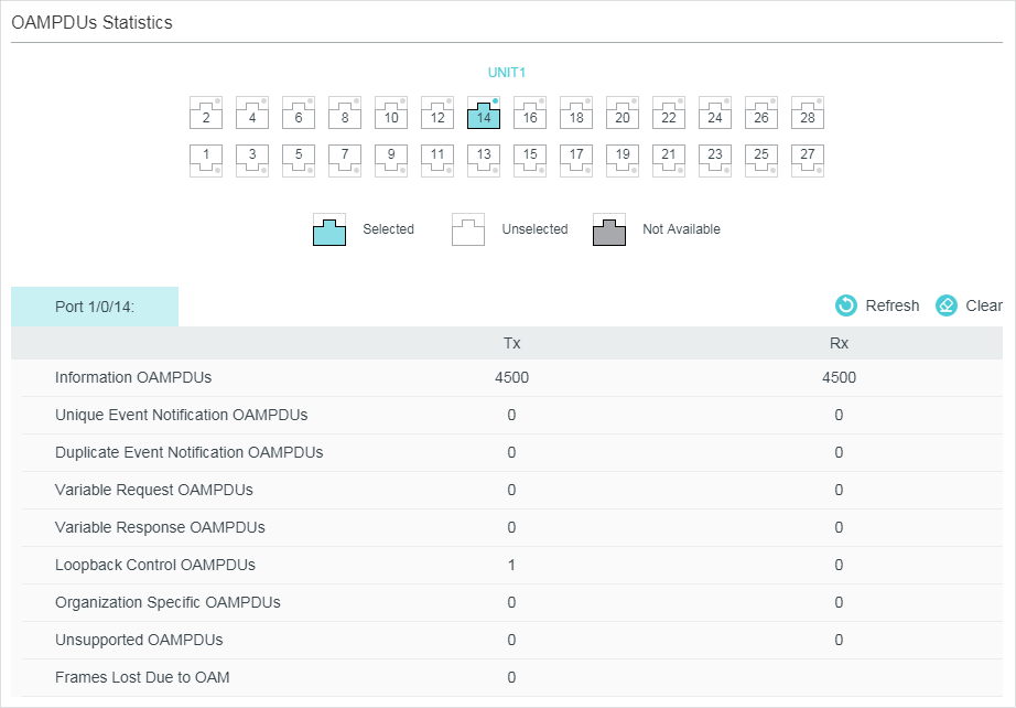
Select a port and view the number of different OAMPDUs transmitted and received on it:
|
Tx |
Displays the number of OAMPDUs that have been transmitted on the port. |
|
Rx |
Displays the number of OAMPDUs that have been received on the port. |
|
Information OAMPDUs |
Displays the number of Information OAMPDUs that have been transmitted or received on the port. |
|
Unique Event Notification OAMPDUs |
Displays the number of Unique Event Notification OAMPDUs that have been transmitted or received on the port. |
|
Duplicate Event Notification OAMPDUs |
Displays the number of Duplicate Event Notification OAMPDUs that have been transmitted or received on the port. |
|
Variable Request OAMPDUs |
Displays the number of Variable Request OAMPDUs that have been transmitted or received on the port. |
|
Variable Response OAMPDUs |
Displays the number of Variable Response OAMPDUs that have been transmitted or received on the port. |
|
Loopback Control OAMPDUs |
Displays the number of Loopback Control OAMPDUs that have been transmitted or received on the port. |
|
Organization Specific OAMPDUs |
Displays the number of Organization Specific OAMPDUs that have been transmitted or received on the port. |
|
Unsupported OAMPDUs |
Displays the number of Unsupported OAMPDUs that have been transmitted or received on the port. |
|
Frames Lost Due To OAM |
Displays the number of frames that are not transmitted successfully on the OAM sublayer but not due to an internal OAM error. |
3.1.2Viewing Event Logs
Choose the menu MAINTENANCE > Ethernet OAM > Statistics > Event Logs Statistics to load the following page.
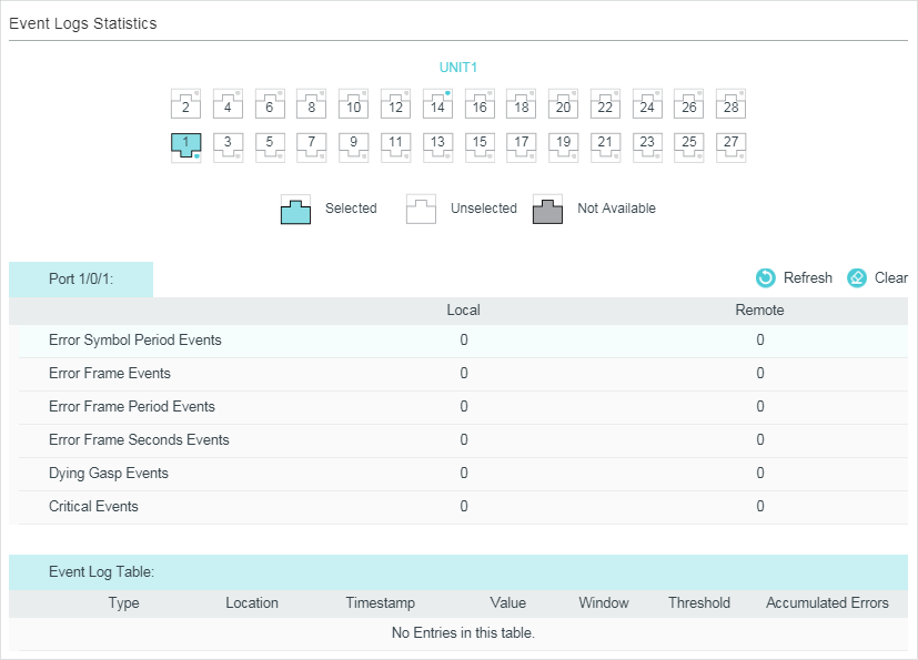
Figure 3-2 Event Logs Statistics
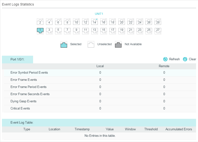
Select a port and view the local and remote event logs on it
|
Local |
Displays the number of link events that have occurred on the local link. |
|
Remote |
Displays the number of link events that have occurred on the remote link. |
|
Error Symbol Period Events |
Displays the number of error symbol period link events that have occurred on the local link or remote link. |
|
Error Frame Events |
Displays the number of error frame link events that have occurred on the local link or remote link. |
|
Error Frame Period Events |
Displays the number of error frame period link events that have occurred on the local link or remote link. |
|
Error Frame Seconds Events |
Displays the number of error frame seconds link events that have occurred on the local link or remote link. |
|
Dying Gasp Events |
Displays the number of Dying Gasp link events that have occurred on the local link or remote link. |
|
Critical Events |
Displays the number of Critical Event link events that have occurred on the local link or remote link. |
Additionally, you can view the detailed information of the event logs in the Event Log Table section.
|
Type |
Displays the types of the link event. |
|
Location |
Displays the location where the link event occurred. |
|
Timestamp |
Displays the time reference when the link event occurred. |
|
Value |
Displays the number of symbol errors or frame errors in the period. |
|
Window |
Displays the period of the link event. |
|
Threshold |
Displays the threshold of the errors. |
|
Accumulated Errors |
Displays the number of errors that have been detected since the OAM feature was last reset. |
3.2Using the CLI
3.2.1Viewing OAMPDUs
On privileged EXEC mode or any other configuration mode, you can use the following command to view the number of OAMPDUs received and sent on the specified port.
|
show ethernet-oam statistics [ interface fastEthernet { port | port-list } | interface gigabitEthernet { port | port-list } | ten-gigabitEthernet { port | port-list }] View the number of different OAMPDUs transmitted and received on the specified port, including Information OAMPDU, Unique Event Notification OAMPDU, Duplicate Event Notification OAMPDU, Loopback Control OAMPDU, Variable Request OAMPDU, Variable Response OAMPDU, Organization Specific OAMPDUs, Unsupported OAMPDU, and Frames Lost Due To OAM (frames that are not transmitted successfully on the OAM sublayer but not due to an internal OAM error). |
The following example shows how to view the transmitted and received OAMDPUs on port 1/0/1.
Switch#show ethernet-oam statistics interface gigabitEthernet 1/0/1
Gi1/0/1
----------------------------------------------------
Information OAMPDU TX : 28
Information OAMPDU RX : 28
Unique Event Notification OAMPDU TX : 0
Unique Event Notification OAMPDU RX : 0
Duplicate Event Notification OAMPDU TX : 0
Duplicate Event Notification OAMPDU RX : 0
Loopback Control OAMPDU TX : 1
Loopback Control OAMPDU RX : 0
Variable Request OAMPDU TX : 0
Variable Request OAMPDU RX : 0
Variable Response OAMPDU TX : 0
Variable Response OAMPDU RX : 0
Organization Specific OAMPDUs TX : 0
Organization Specific OAMPDUs RX : 0
Unsupported OAMPDU TX : 0
Unsupported OAMPDU RX : 0
Frames Lost Due To OAM : 0
3.2.2Viewing Event Logs
On privileged EXEC mode or any other configuration mode, you can use the following command to view the local and remote event logs on the specified port.
|
show ethernet-oam event-log [ interface fastEthernet { port | port-list } | interface gigabitEthernet { port | port-list } | ten-gigabitEthernet { port | port-list }] View the local and remote event logs on the specified port. An event list will be displayed, including the following information: Type: Displays the type of the link event. Location: Displays the location where the link event occurred (local or remote). Timestamp: Displays the time reference when the link event occurred. And the number of local and remote event logs will be displayed, including the following events: Error Symbol Event: Displays the number of error symbol period link events that have occurred on the local link or remote link. Error Frame Event: Displays the number of error frame link events that have occurred on the local link or remote link. Error Frame Period Event: Displays the number of error frame period link events that have occurred on the local link or remote link. Error Frame Seconds Event: Displays the number of error frame seconds link events that have occurred on the local link or remote link. Dying Gasp: Displays the number of Dying Gasp link events that have occurred on the local link or remote link. Critical Event: Displays the number of Critical Event link events that have occurred on the local link or remote link. |
The following example shows how to view the event logs on port 1/0/1.
Switch#show ethernet-oam event-log interface gigabitEthernet 1/0/1
Gi1/0/1
Event Listing
-----------------------------------------------------------
Type Location Time Stamp
--------------------- ------------- --------------------
Critical Event Remote 2016-01-01 08:08:00
Local Event Statistics
Error Symbol Event : 0
Error Frame Event : 0
Error Frame Period Event : 0
Error Frame Seconds Event : 0
Dying Gasp : 0
Critical Event : 0
Remote Event Statistics
Error Symbol Event : 0
Error Frame Event : 0
Error Frame Period Event : 0
Error Frame Seconds Event : 0
Dying Gasp : 0
Critical Event : 1
4.1Network Requirements
A network administrator wants to manage and troubleshoot the network more effectively, requiring that the link failure and frame errors on the link between Switch A and Switch B can be monitored and reported via the Ethernet OAM feature.
Figure 4-1 Network Topology

4.1.1Configuration Scheme
To meet the requirement, configure OAM on port 1/0/1 of each switch. Two features can be configured: Link Monitoring and Remote Failure Indication. With Link Monitoring, the frame errors on the link can be monitored and reported; with Remote Failure Indication, the link failure can be monitored and reported.
The overview of configuration is as follows:
1)Enable OAM and configure the OAM mode for port 1/0/1 on each switch. Here we configure OAM mode of the port on Switch A as active, and that on switch B as passive.
2)Configure Link Monitoring for port 1/0/1 on each switch.
3)Configure Remote Failure Indication for port 1/0/1 on each switch.
Demonstrated with T2600G-28TS, the following sections provide configuration procedure in two ways: using the GUI and using the CLI.
4.1.2Using the GUI
The configurations for Switch A and Switch B are similar. We take Switch A as an example.
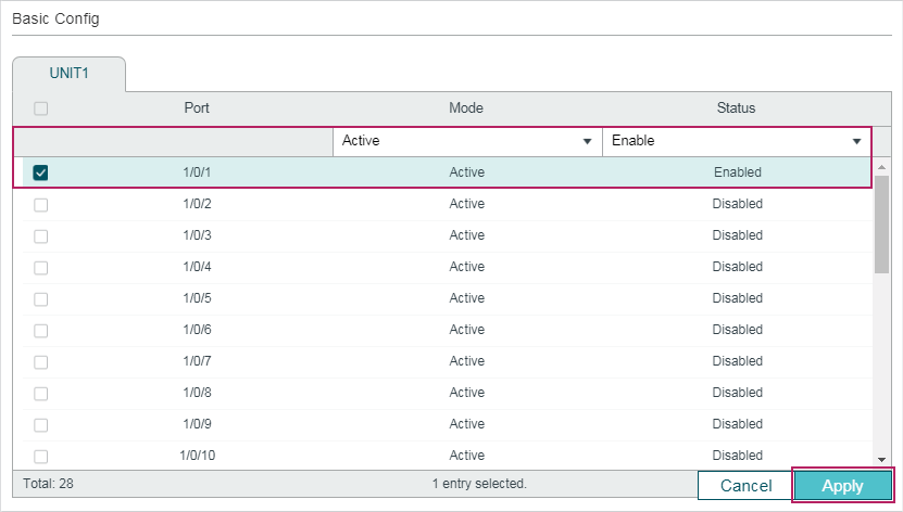
1)Choose the menu MAINTENANCE > Ethernet OAM > Basic Config > Basic Config to load the following page. Select port 1/0/1, and configure the mode as Active and the state as Enable. Click Apply.
Figure 4-2 Basic Configuration
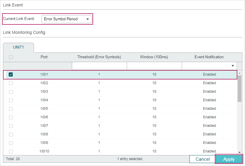
2)Choose the menu MAINTENANCE > Ethernet OAM > Link Monitoring to load the following page. Select each Link Event type and configure the relevant parameters on port 1/0/1. Make sure that Event Notification is enabled and specify the threshold and window according to your needs. Here we keep the default parameters. Click Apply.
Figure 4-3 Link Monitoring Configuration
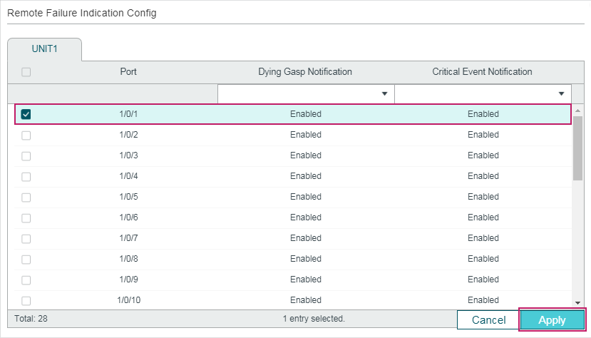
3)Choose the menu MAINTENANCE > Ethernet OAM > Remote Failure Indication to load the following page. Select port 1/0/1 and enable Dying Gasp Notification and Critical Event Notification. Click Apply.
Figure 4-4 Remote Failure Indication Configuration
4)Choose the menu MAINTENANCE > Ethernet OAM > Basic Config > Discovery Info to load the following page. Select port 1/0/1 to check the OAM status. When the connection status becomes Operational, it indicates that OAM connection has been established and OAM works normally.
Figure 4-5 Discovery Infomation
5)Click  to save the settings.
6)Choose the menu MAINTENANCE > Ethernet OAM > Statistics > Event Log to load the following page. Select port 1/0/1 to view the event logs on the port.
Figure 4-6 OAM Event Logs
4.1.3Using the CLI
1)Enable OAM and configure OAM mode as active on port 1/0/1.
Switch_A#configure
Switch_A(config)# interface gigabitEthernet 1/0/1
Switch_A(config-if)#ethernet-oam
Switch_A(config-if)#ethernet-oam mode active
2)Configure Link Monitoring on the port. Enable Event Notification and keep the threshold and window as the default.
Switch_A(config-if)#ethernet-oam link-monitor symbol-period notify enable
Switch_A(config-if)#ethernet-oam link-monitor frame-period notify enable
Switch_A(config-if)#ethernet-oam link-monitor frame notify enable
Switch_A(config-if)#ethernet-oam link-monitor frame-seconds notify enable
3)Configure Remote Failure Indication on the port. Enable Dying Gasp Notification and Critical Event Notification.
Switch_A(config-if)#ethernet-oam remote-failure critical-event notify enable
Switch_A(config-if)#ethernet-oam remote-failure dying-gasp notify enable
Switch_A(config-if)#ethernet-oam link-monitor frame-period notify enable
Switch_A(config-if)#ethernet-oam link-monitor frame notify enable
Switch_A(config-if)#end
Switch_A#copy running-config startup-config
Verify the Configuration
Verify the configuration of OAM:
Switch_A#show ethernet-oam configuration interface gigabitEthernet 1/0/1
Gi1/0/1
-----------------------------------------------------------
OAM : Enabled
Mode : Active
Dying Gasp : Enabled
Critical Event : Enabled
Remote Loopback OAMPDU : Not Processed
Symbol Period Error
Notify State : Enabled
Window : 1000 milliseconds
Threshold : 1 Error Symbol
Frame Error
Notify State : Enabled
Window : 1000 milliseconds
Threshold : 1 Error Frame
Frame Period Error
Notify State : Enabled
Window : 148810 Frames
Threshold : 1 Error Frame
Frame Seconds Error
Notify State : Enabled
Window : 60000 milliseconds
Threshold : 1 Error Seconds
Verify the OAM connection:
Switch_A#show ethernet-oam status interface gigabitEthernet 1/0/1
Gi1/0/1
Local Client
-----------------------------------------------------------
OAM : Enabled
Mode : Active
Max OAMPDU : 1518 Bytes
Remote Loopback : Supported
Unidirection : Not Supported
Link Monitoring : Supported
Variable Request : Not Supported
PDU Revision : 2
Operation Status : Operational
Loopback Status : No Loopback
Remote Client
-----------------------------------------------------------
Mode : Passive
MAC Address : 18-A6-F7-DB-63-81
Vendor(OUI) : 000aeb
Max OAMPDU : 1518 Bytes
Remote Loopback : Supported
Unidirection : Not Supported
Link Monitoring : Supported
Variable Request : Not Supported
PDU Revision : 1
Loopback Status : No Loopback
Vendor Information : 00000000
View the OAM event logs:
Switch_A#show ethernet-oam event-log interface gigabitEthernet 1/0/1
Gi1/0/1
Event Listing
-----------------------------------------------------------
Type Location Time Stamp
---------------- ------------- --------------------
Critical Event Remote 2016-01-01 08:08:00
Local Event Statistics
Error Symbol Event : 0
Error Frame Event : 0
Error Frame Period Event : 0
Error Frame Seconds Event : 0
Dying Gasp : 0
Critical Event : 0
Remote Event Statistics
Error Symbol Event : 0
Error Frame Event : 0
Error Frame Period Event : 0
Error Frame Seconds Event : 0
Dying Gasp : 0
Critical Event : 1
Default settings of Ethernet OAM are listed in the following tables.
Table 5-1Ethernet OAM
|
Parameter |
Default Setting |
|
Basic Config |
|
|
Mode |
Active |
|
Status |
Disabled |
|
Link Monitoring |
|
|
Error Symbol Period |
Threshold : 1 error symbol Window: 10*100 ms Event Notification: Enabled |
|
Error Frame |
Threshold : 1 error frame Window: 10*100 ms Event Notification: Enabled |
|
Error Frame Period |
Threshold : 1 error frame Window: 1488100 frames Event Notification: Enabled |
|
Error Frame Seconds |
Threshold : 1 error second Window: 600*100 ms Event Notification: Enabled |
|
Remote Failure Indication |
|
|
Dying Gasp Notification |
Enabled |
|
Critical Event Notification |
Enabled |
|
Remote Loopback |
|
|
Received Remote Loopback |
Ignore |