How to Configure Management VLAN on TP-Link Smart and Managed Switches Using the New GUI
Introduction
Management VLAN provides a safer method to manage the switch. With management VLAN configured, only the hosts in the management VLAN can access switches’ GUI.
Network Requirements
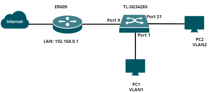
As the following topology shows, PC1 and PC2 are connected to port 1 and port 21 of the switch. The switch (TL-SG3428X) is connected to the internet via a router through port 9. The IP address of the switch is 192.168.0.100, which is assigned by the router (ER605). In this example, we will configure management VLAN to only allow the hosts in VLAN2 to access the GUI of the switch.
Configuration Overview
1. Create a VLAN interface on the router
2. Create the corresponding VLAN on the switch
3. Create an access control rule
4. Verification
Configuration Steps
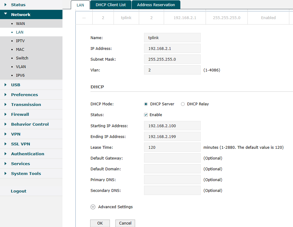
Step 1. Log in to the router’s GUI and navigate to Network → LAN to add a new VLAN interface — VLAN 2.
Step 2. Log in to the GUI of the switch and navigate to L2 Features → VLAN → 802.1Q VLAN → VLAN Config to add a new entry for VLAN — VLAN2. The uplink port of the switch should be tagged.
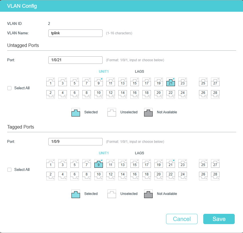
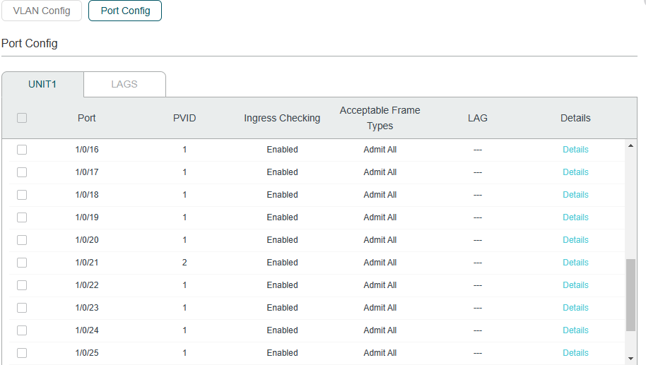
Then navigate to Port Config and change the PVID of Port 21 to 2.
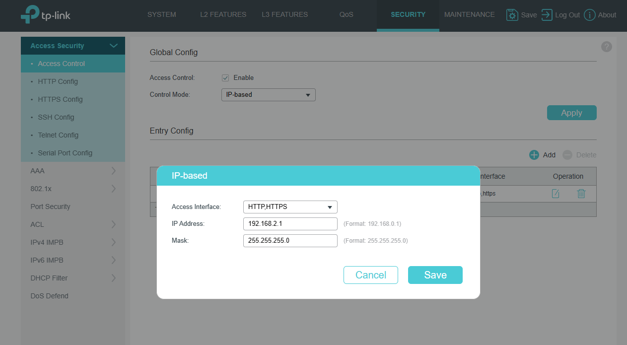
Step 3. Navigate to Security → Access Security → Access control to create an IP-based ACL (Access Control List).
Specify the Access interface as HTTP and HTTPS, and only allow devices in 192.168.2.1/24 to access the GUI of switch.
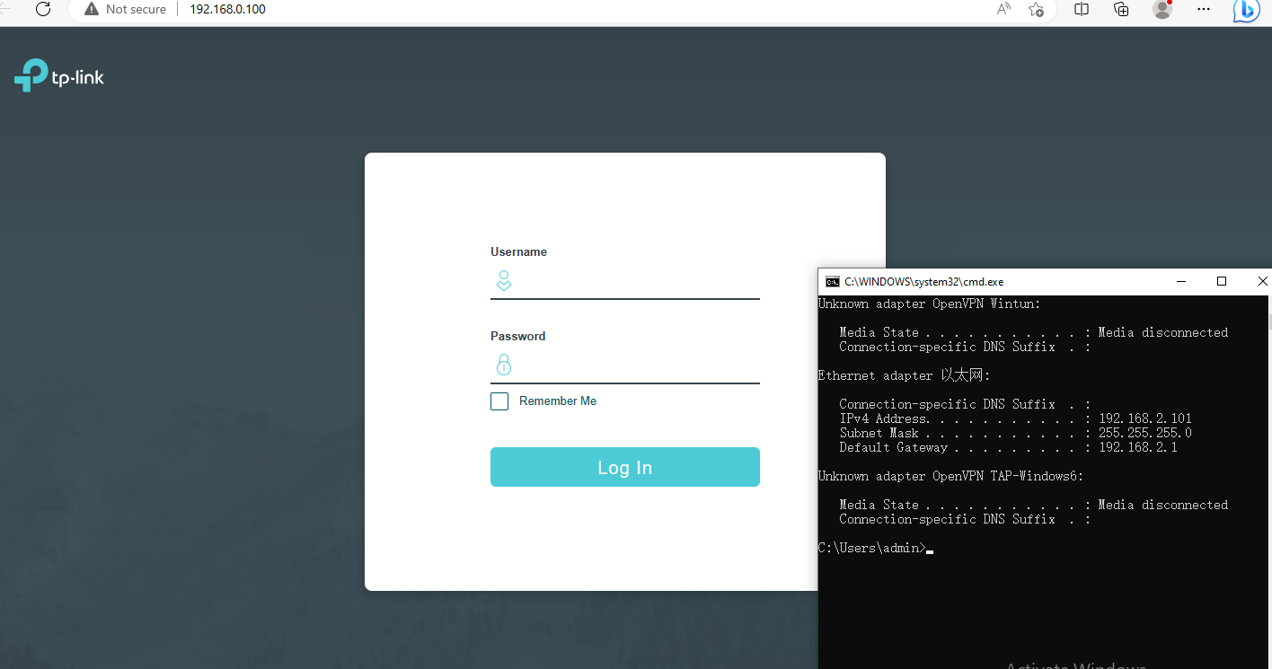
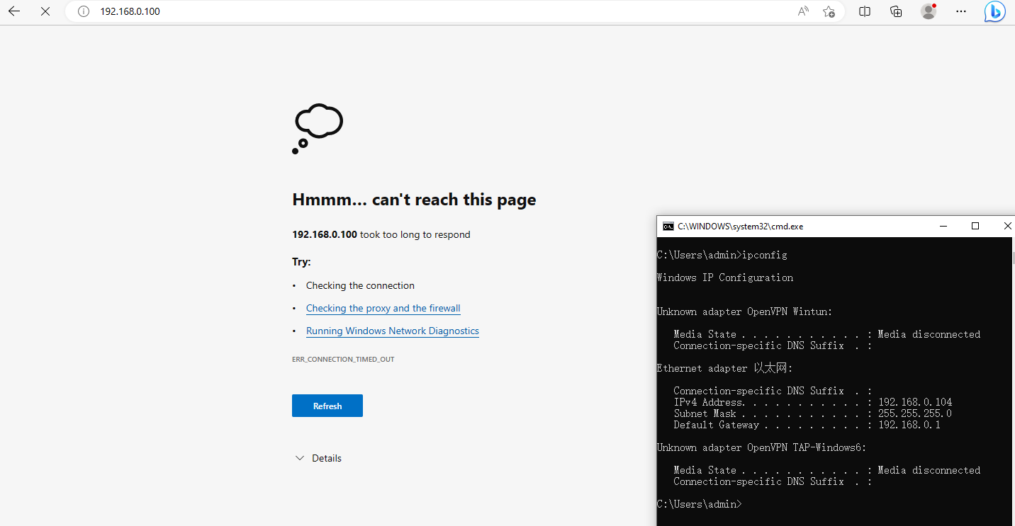
Step 4. Verification
Lastly, you can verify whether the settings have been successfully applied. For example: PC2 in VLAN2 can access 192.168.0.100; however, PC1 cannot.
Byla tato FAQ užitečná?
Vaše zpětná vazba nám pomůže zlepšit naše webové stránky